◆This is an all – round system that has high functional efficiency, economical efficiency, and safety.
This Quick Die Change System is very reliable since it has been designed and
developed trigeminally for high functional efficiency, economical efficiency, and
safty in die exchanging operation of the press, injection molding machine, die
casting machine, etc. This system is applicable to machine tool processing field of
automated machine as well as die exchange.
•Functional efficiency : This system is constituted of various components that
endure even in extreme conditions, such as high speed,
vibration, high temperature, or moisture. With the high
reliability and proven high efficiency, the performance is
not limited in any purposes.
•Economical efficiency : The exchange time even for a large die is reduced due
to its automatic exchanging type. Furthermore, the
uniform clamping force protects the die and improves
the precision of the product.
•Safety : Due to the Non-Touch Clamp and the mechanical Lock Clamp design,
a dangerous manual operation is not required and there is no danger of
die falling. It also has the interacting safety control device.
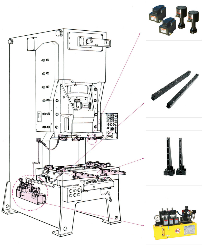
◆Preparations of the outside part and inside part of the Quick Die Change System
•Outside part preparation : Available operations while the machine is operating.
i.e. preparing operations for die exchange while the press or injection molding machine is operating, such as placement, transfer,
maintenance of die, etc.
【die cart, dies(molds)stroke beam, forklift, hoist, overhead crane, etc】
•Inside part preparation : Operations that should be done only after stopping the machine.
i.e. die exchange operations after stopping the press or injection molding machine. The inside part is constituted of the following
components.

◆Selecting CLAMP
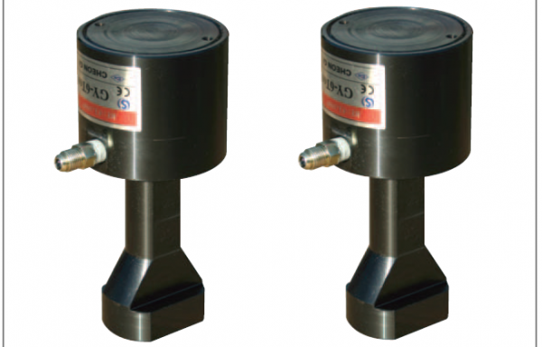
•Hi-Clamp : Semi-automatic type, i.e, an operator should move the position of
the Clamp to the Dies(molds)and clamping is done by hydraulic
pressure.
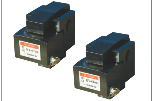
•Auto-Clamp : Differently form the Hi-Clamp automatic type, which does not
require an operator.
•The overall clamping force here means the clamping force between the upper
and the lower part. Generally, the standard of the overall champing force is
10~20% of the machine power.
•The ratio of the overall clamping force can be obtained by the following formula
or the bolt size in case of the upper part-60%. the lower part-40%
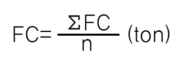
FC : Unit clamping force(ton)
n : No. of clamp to be used
ΣFC : Overall clamping force(ton)
Note) The unit clamping force per bolt or clamping force is an approximate valve.
Select the clamping force according to the type of the operation and conditions.
BOLT SIZE M16 M18 M20 M24 M30 M38
Clamping force (ton) 1-3 2-4 4-6 6-10 8-15 15-20
◆Required clamping time
•The required clamping time can be obtained by the following formula.
t = (ΣV×60)/(0.7~0.8)×Qf)+1(sec)
V = Clamp displaced volume(ml)
Qf = Pump free emission volume(ml/min)
•Since the required clamping time varies with the constituent circuit, clamp type,
piping condition, oil viscosity, condition of air supply, etc, allow 20~30% time to
spare.
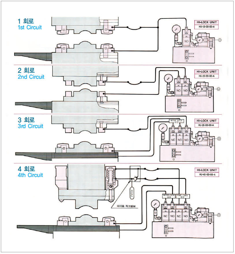
◆Duration of clamping force & safety circuit
•Since the line pressure(clamping force)is maintained 50% or more by the Nonleak
valve as shown below even in case of power failure or breaking-off air
supply, falling of Die(molds)is prevented.
•Due to the Inter-lock circuit between the lower part of the clamp and the die
lifter, the false operation of the die lifter or descending of the slide is prevented.
•With the hydraulic pressure in the circuit drops below the standard, the
Pressure switch in the Hi-lock unit detects it and makes it possible to check it
by the emergency stop and the lamp. Therefore, safety is maintained due to
the inter-lock circuit formed when installed with the basic circuit of the
machine.
•Since the hydraulic pressure gauge is equipped as a standard device, the
pressure condition can be checked at a glance.
